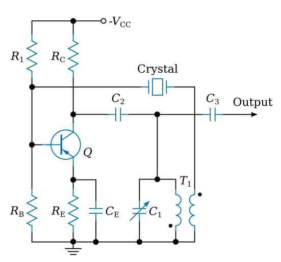
Crystal oscillators have high-frequency stability and a high-Quality factor compared to RC and LC tuned circuit oscillators. It has two electrodes that supply signals to the crystal. Hence the oscillator circuit containing piezoelectric crystal is called a crystal oscillator. The quartz crystal is also known as piezoelectric crystal. You don't need to do that.The crystal oscillator is a quartz crystal used as a frequency selective element. I used the tutorial pacakges so I can show the progress of the classes as we moved from tutorial to tutorial.

Change that to something like sdr or whatever you called your project. That said, you probablly don't want to put everything in a top level package called tutorial1.

You don't have to use packages if you don't want, but as our collection of classes grows, it is helpful for them to be organized into packages. I have also put all of the files in a package "tutorial1". I have given it the package name "signal" and therefore stored it in a sub-directory called signal. We must therefore name the file Oscillator.java, to match the class name. If you are new to Java have a look at my Quick Java Tutorial, which will explain that each class goes in its own source file. If you want to work in Python, click the bar below to show the example Python code, otherwise click Java. Pulled together in a class it looks like the below. We will call nextSample each time we need a new sample of our waveform. That means our 1200Hz wave will make one complete cycle in 48000 / 1200 = 40 samplesįinally, we create a method called nextSample (note that in Python I will follow the typical naming convention using lower case and underscores for functions/methods, so it will be next_sample). We define the phase increment as 2 pi times frequency / samples per second. One complete sample of our waveform has 2 pi radians. The frequency is relative to the sample rate and is used to set the amount that the phase increases for each sample. This will save us from calculating the sine value every time we need a sample of our waveform. In Java or Python we can create this with a short class called Oscillator which has one constructor that takes the requested frequency, the sample rate in samples per second and then builds a table of sine values.
#OSCULATOR TUTORIAL GENERATOR#
In software our sine wave generator is called a Numerically Controlled Oscillator or NCO.
#OSCULATOR TUTORIAL CODE#
Later we will add some code to draw graphs on the screen and eventually use that as part of our radio. Given everything is digital we can cut/paste and graph with a spreadsheet. One approach is to print out values and graph them. We need to be able to see the results of what we do. You will see other formats and we will have to convert to/from them for storage in files or to pass in and out of hardware sound cards. We will use values between -1 and 1 to represent our signals. In the digital realm we do not produce a continuous wave, but instead deal with samples. Let's create an oscillator and a piece of test equipment that we can use to measure it.Īn analog oscillator typically has a tuned circuit and we pick C and L values to set the frequency. We also use a radio (software defined or otherwise) to hear and see our signals. On the test bench we have a DVM, an oscilloscope and perhaps a spectrum analyzer. Like homebrew electronics, we need to be able to measure and see the results of our experiments. This is a good place for us to start our adventure into software defined radio. They are a key part of the radio architecture, perhaps as a VFO or as a crystal oscillator for a mixer. Perhaps the first homebrew project I built that was not directly from a kit was an oscillator. The Java files for this tutorial are available on /ac2cz/SDR

Software Defined Radio for the Radio Amateur Index | Next Tutorial


 0 kommentar(er)
